Series And Parallel Circuit - 5 Differences Between Series And Parallel Circuits Important Question For Interview - The components are arranged one after another in.
Series And Parallel Circuit - 5 Differences Between Series And Parallel Circuits Important Question For Interview - The components are arranged one after another in.. Examples to solve series circuits. Series circuits are useful if you want a warning that one of the components in the circuit has failed. A circuit in which two of more electrical resistances or loads are connected across the same voltage source is called a parallel circuit. How to solve resistors in series circuits. Not all circuits are simple series or parallel arrangements.
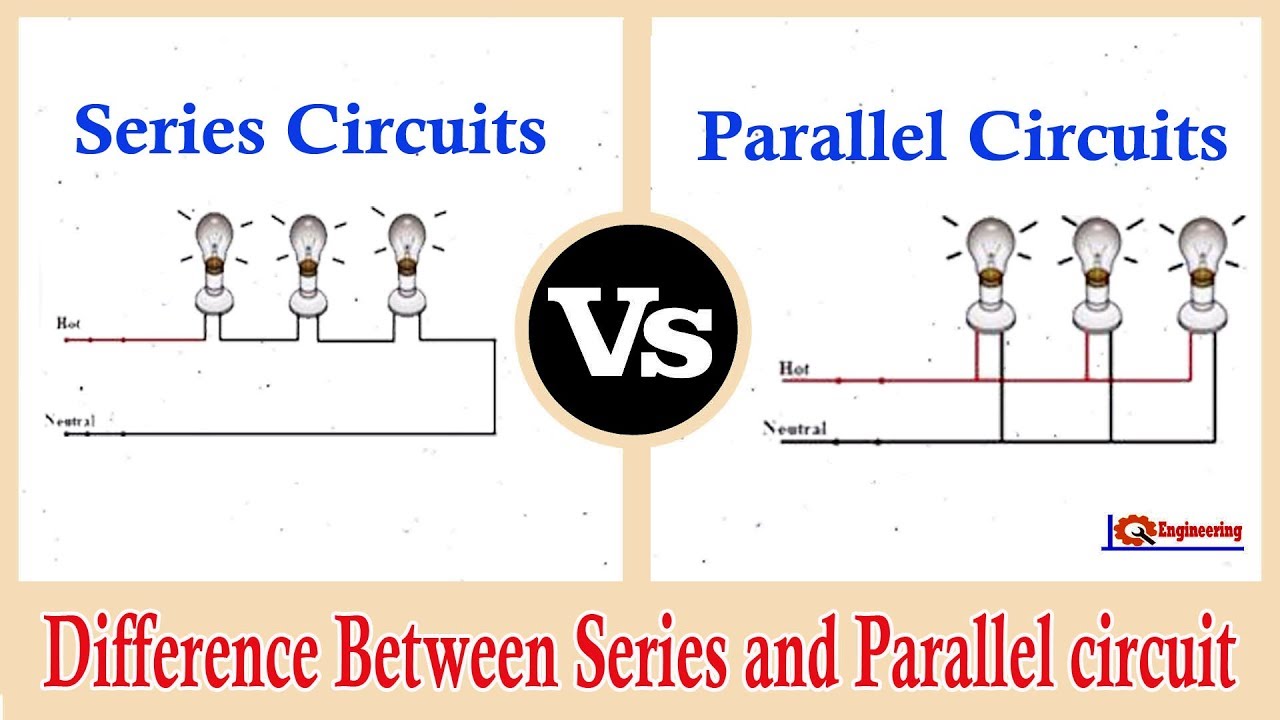
Thus, the troubleshooting series circuit is difficult than a parallel circuit. How does adding resistors in parallel affect the current strength? Unlike a series circuit, it's not ' one out all out' !. (5) parallel circuit obeys the kirchhoff's current law. Provide definitions of series and parallel circuits and discuss the differences.
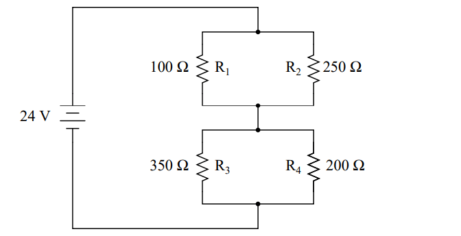
What Is A Series Parallel Combination Circuit Instrumentationtools from instrumentationtools.com The current flows through each resistor in turn. Parallel circuit is said to be connected in parallel if it has multiple paths for electricity to flow through. So far we have discussed series dc circuits and parallel dc circuits separately, but in practice, the electrical circuit is generally a combination of both series circuits and parallel circuits. The parallel circuit can be easily repaired. In a series circuit, a common current flows through all. How to solve resistors in series circuits. Examples to solve series circuits. Connecting loads in series and parallel affects the current, potential difference.
In the series circuit, the components in the circuit are connected one after the other or we can say in a cascaded fashion.
Neither lamp feels the full voltage of the battery. Series and parallel describes two different types of circuit arrangements. Parallel circuit is said to be connected in parallel if it has multiple paths for electricity to flow through. The parallel circuit can be easily repaired. So far we have discussed series dc circuits and parallel dc circuits separately, but in practice, the electrical circuit is generally a combination of both series circuits and parallel circuits. Thus, the troubleshooting series circuit is difficult than a parallel circuit. How passive components act in these configurations. The current flowing through these circuits remains same at any point but the voltage varies. Series and parallel arrangements are two basic configurations in which we can arrange the electrical components. In parallel circuits different components are connected on different branches of the wire. Properties of parallel circuit (1) the voltage drop across each component is equal to the source voltage or supply voltage. Series connected circuits consist of two or more active and/or passive devices connected in series. How does adding resistors in parallel affect the current strength?
If you follow the circuit diagram from one side of the cell to the other, you can only pass through all the different. The total voltage drop across both resistors (points a to c) is going to however, when components are in parallel, the current actually splits up inside of the circuit and then recombines later. Serial circuit and parallel circuit and current flow in it. In a series circuit, a common current flows through all. The main difference between series and parallel circuits is that, in series circuits, all components are connected in series so that they all share the same current whereas, in parallel.
Series And Parallel Circuits Series Vs Parallel Difference Between Series And Parallel Circuits Youtube from i.ytimg.com Electrical circuits can become immensely complicated. A simple schematic of a. Though you can sum of the voltages around a closed loop as equal to zero in a parallel circuit, summing up the currents is more complicated. Introduction so far we have discussed circuits with only two components, a source of current (such as a battery) and a single resistance (such as in this circuit, the current that comes out of the battery passes through both lamps. Components in a circuit can be connected in series or in parallel. Voltmeter are placed in parallel with the component. Series and parallel arrangements are two basic configurations in which we can arrange the electrical components. Simple circuits (ones with only a few components) are usually fairly straightforward for beginners to understand.
This physics video tutorial explains series and parallel circuits.
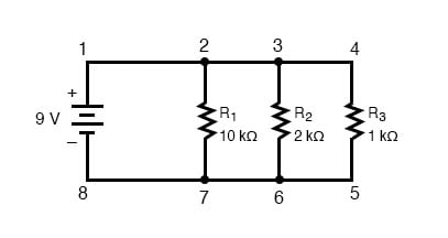
The primary difference between the series circuit and the parallel circuit is that more than one path is provided for the current in the parallel. Series and parallel arrangements are two basic configurations in which we can arrange the electrical components. Instead of setting the sum of the current values themselves that enter a node equal to the sum of the current values leaving. One from 1 to 2 to 5 to 6 and back to 1 again series and parallel resistor configurations have very different electrical properties. Most have resistors in parallel and in series. Provide definitions of series and parallel circuits and discuss the differences. How series and parallel circuits differ pg. A simple schematic of a. The parallel circuit can be easily repaired. The current flowing in a series circuit through all of its components is considered the same because they are attached in series. We'll explore the properties of each configuration in the sections to come. These circuits are used in everyday life in different appliances. Connecting loads in series and parallel affects the current, potential difference.
How series and parallel circuits differ pg. Provide definitions of series and parallel circuits and discuss the differences. How to solve resistors in series circuits. A series circuit is one in which there is only one pathway for the electric current to follow. Connecting loads in series and parallel affects the current, potential difference.
Simple Parallel Circuits Series And Parallel Circuits Electronics Textbook from www.allaboutcircuits.com So far we have discussed series dc circuits and parallel dc circuits separately, but in practice, the electrical circuit is generally a combination of both series circuits and parallel circuits. How does adding resistors in parallel affect the current strength? In the series circuit, equivalent voltage is the sum of the voltage across all the serial connected components.calculating the value of the potential difference is veq= (v1+v2+v3+ the series circuit is not so easy to repair as compare parallel circuit. Series and parallel circuits components in a circuit can be connected in series or parallel. A series arrangement of components is where they are 13.10: A series circuit is one in which there is only one pathway for the electric current to follow. In figure 2's circuit the battery is providing 10v. A series circuit is shown in the diagram above.
There the total current or supply current is equal to the sum of the currents through individual components and it depends on the value of their resistance.
Unlike a series circuit, it's not ' one out all out' !. In series circuit it follows that if there is a break in any part of the circuit, no current flows.this is why fuses, circuit breakers and safety switches are a break in one circuit doesn't affect the others. Voltage drops in series circuits. In the series circuit, if one component is damaged then other components will not get supply. If you follow the circuit diagram from one side of the cell to the other, you can only pass through all the different. This circuit is a polynomial plotter, which allows users to plot polynomials and evaluate functions at most circuits are not just a series or parallel circuit; Voltmeter are placed in parallel with the component. One from 1 to 2 to 5 to 6 and back to 1 again series and parallel resistor configurations have very different electrical properties. The components in a series circuit are usually attached in a cascaded fashion or can say attached one after the other. In figure 2's circuit the battery is providing 10v. Most have resistors in parallel and in series. Series and parallel arrangements are two basic configurations in which we can arrange the electrical components. The current flowing in a series circuit through all of its components is considered the same because they are attached in series.
You have just read the article entitled Series And Parallel Circuit - 5 Differences Between Series And Parallel Circuits Important Question For Interview - The components are arranged one after another in.. You can also bookmark this page with the URL : https://klaixelt.blogspot.com/2021/04/series-and-parallel-circuit-5.html
Share Awesome
Belum ada Komentar untuk "Series And Parallel Circuit - 5 Differences Between Series And Parallel Circuits Important Question For Interview - The components are arranged one after another in."
Belum ada Komentar untuk "Series And Parallel Circuit - 5 Differences Between Series And Parallel Circuits Important Question For Interview - The components are arranged one after another in."
Posting Komentar